


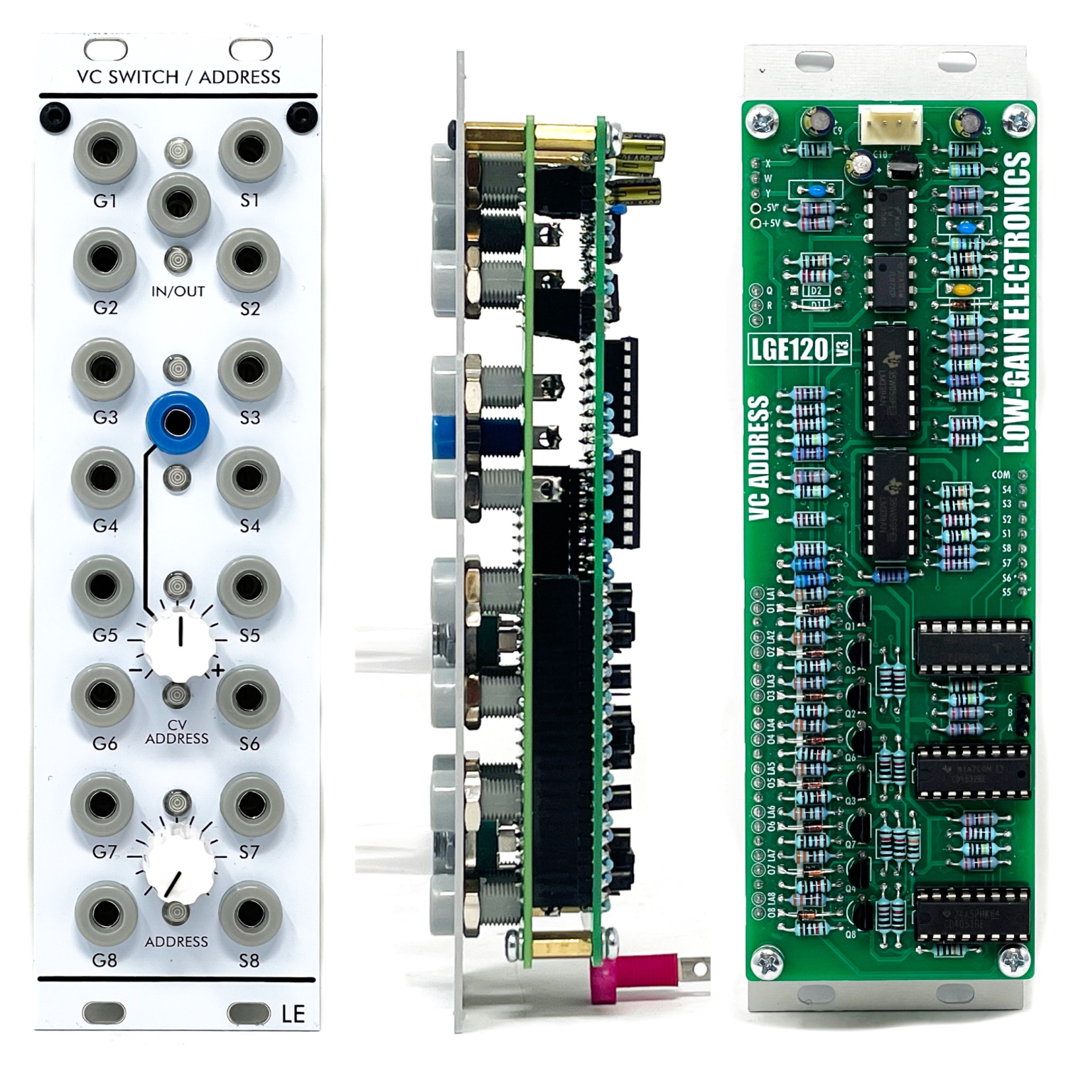
VC Switch / Address
DESCRIPTION8:1 Bidirectional voltage controlled switch with Rail to Rail signal switching operation, and 8 stage gate outputs.
DETAILSDIY PCB/Panel or Assembled Module
Current: TBD
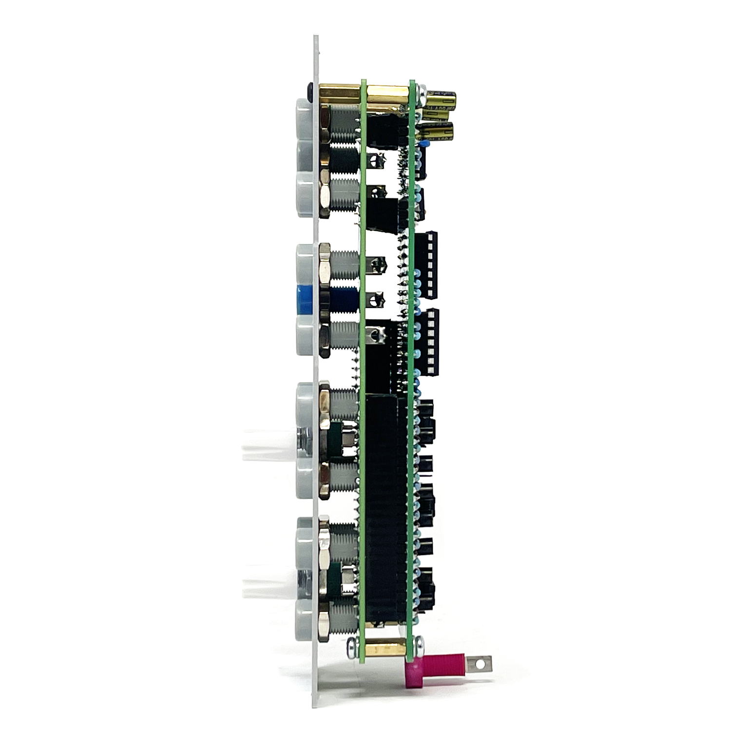
PCB Size: 6” x 2”
DESCRIPTION8:1 Bidirectional voltage controlled switch with Rail to Rail signal switching operation, and 8 stage gate outputs.
DETAILSDIY PCB/Panel or Assembled Module
Current: TBD
PCB Size: 6” x 2”
DESCRIPTION8:1 Bidirectional voltage controlled switch with Rail to Rail signal switching operation, and 8 stage gate outputs.
DETAILSDIY PCB/Panel or Assembled Module
Current: TBD
PCB Size: 6” x 2”
The VC Switch/Address is an 8 position bi-directional switched controlled by a window comparator. Manual control over the switch position is done by the “Address” knob (Internal bias control of the window comparator). The CV Address input has a bipolar attenuator so you can Set the switch to any position and either add or subtract from that switch position. Each switch position also has a dedicated Gate output jack. This becomes very handy to trigger envelopes, sequencer stages, tuneable offsets, complex pulse generators. Outputs are stackable via OR logic technology allowing for interesting burst generation or oscillator shaping (if modulated at audio rates). Send multiple waveforms from oscillators to create complex waveforms depending on the position of one of the original waveforms! G1-G8 - Gate outputs, S1-S8 = Switch I/O
Below show’s how to modify the module for 0-5V offset operation. I found this more useful than a +/-5V offset and will update on next restock.
Production modules will ship with this modification already done.


** 4U Modular is a term used for the format most commonly known as “Serge Format” or “Loudest Warning Format”. Out of respect for the ever growing format, 4U Modular is the easiest way to refer to it. More Specifically it refers to the panel height and mounting hole style. 4U Modular will patch up just fine with other 4U "Serge" formats such as "Random Source", but it will not mount in RS boats or Buchla Boats (or power off Buchla power for that matter). An info page about this will be added to the website soon to make this a lot more easy to understand.
DIY Build Information:
LGE120 Main Board Bill of Materials
LGE120 Main Board Designator Layout
LGE120 Main Board Schematic
LGE120C I/O Board Bill of Materials
LGE120C I/O Board Designator Layout
LGE120C I/O Board Schematic
LGE120 Panel Art
Mechanical Parts BOM generally required for building Low-Gain Electronics Modules
Details:
PCB Size: 6” x 2”
Current Draw: TBD