Slope Filter
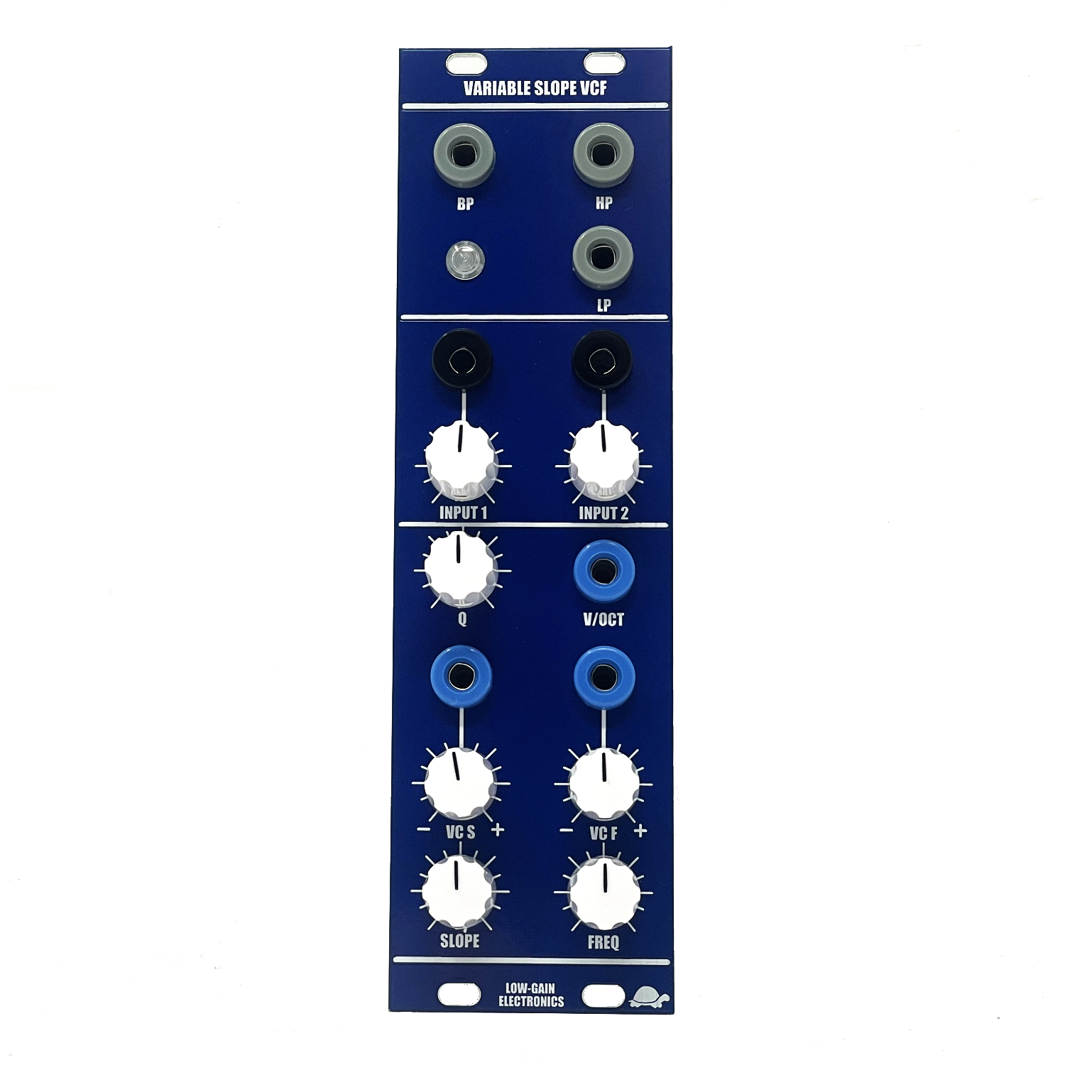
A classic highly resonant 2-pole filter based around a classic 4U Modular Filter design with HP, LP, and BP outputs.
A classic highly resonant 2-pole filter based around a classic 4U Modular Filter design with HP, LP, and BP outputs.
A classic highly resonant 2-pole filter based around a classic 4U Modular Filter design with HP, LP, and BP outputs.
From the original Catalog
“The VARIABLE SLOPE VCF (VCFS) offers unique control of sound quality offered by no other synthesizer manufacturer. All VCF's offer voltage control of the cut--off frequency, that. is, control of which frequencies the filter lets pass . The VCFS allows the amount of
filtering to be dynamically controlled as well, from barely perceptible filtering to highly resonant, sharp cut-offs . With the variable slope control in the center position, the VCFS acts as a typical flat-response VCF, with high, low, and band--pass outputs
available simultaneously . The slope of the cutoff is 12 db/octave . As the control is moved toward the maximum position, the resonance of the filter increases, so that the cutoff becomes sharper . Although the VCFS will not ring like the VCFQ, it will resonate enough at the
maximum setting to pick out harmonics from a complex; signal input . As the control is moved to the minimum position, the cut-off slope will decrease to 6 db/octave. This type of change of filter, slope has been found to be an effective synthesis technique corresponding well with
some of the transformations in acoustic instrument sounds . There are two signal inputs to the VCFS which can be mixed and manually crossfaded from the associated knob ..”
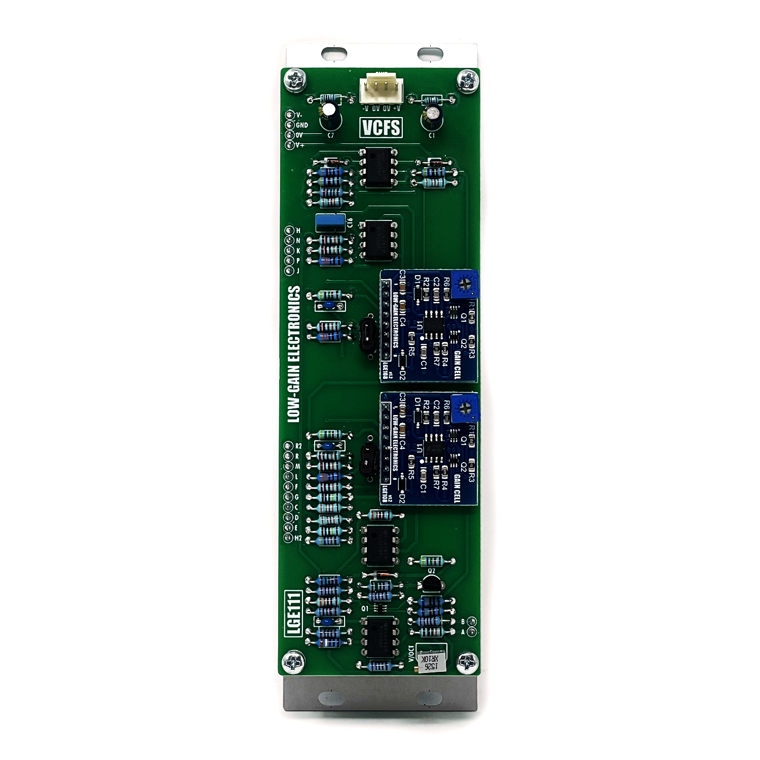
LGE111 Main board pcb’s include a set of 2 LGE108 Gain Cells that have all the SMD parts pre-assembled. You will still need to install trim pot (100K), and headers (and calibrate).
LGE108 Gain cells can be purchased on their own as well.
Build Info: (Coming Soon!)
LGE111 Main PCB Bill of Materials
LGE111 Main PCB Schematic
LGE111 Main PCB Designators
LGE111 Main PCB Modification (Simple Jumper)
LGE111C I/O PCB Bill of Materials
LGE111C I/O PCB Schematic (wiring diagram)
LGE111C I/O PCB Designators
LGE108 Gain Cell Schematic
LGE108 Gain Cell PCB Designators
LGE108 Gain Cell Testing/Calibration circuit
LGE108 Gain Cell Requires 100K Trim Pot to be installed prior to installing onto pcb.
Mechanical Parts BOM generally required for building Low-Gain Electronics Modules
** 4U Modular is a term used for the format most commonly known as “Serge Format” or “Loudest Warning Format”. Out of respect for the ever growing format, 4U Modular is the easiest way to refer to it. More Specifically it refers to the panel height and mounting hole style. 4U Modular will patch up just fine with other 4U "Serge" formats such as "Random Source", but it will not mount in RS boats or Buchla Boats (or power off Buchla power for that matter). An info page about this will be added to the website soon to make this a lot more easy to understand.
Assembled Modules are built to order, please be patient when ordering. Use the contact page if you have any questions or requirements!


