Bandwidth Filter
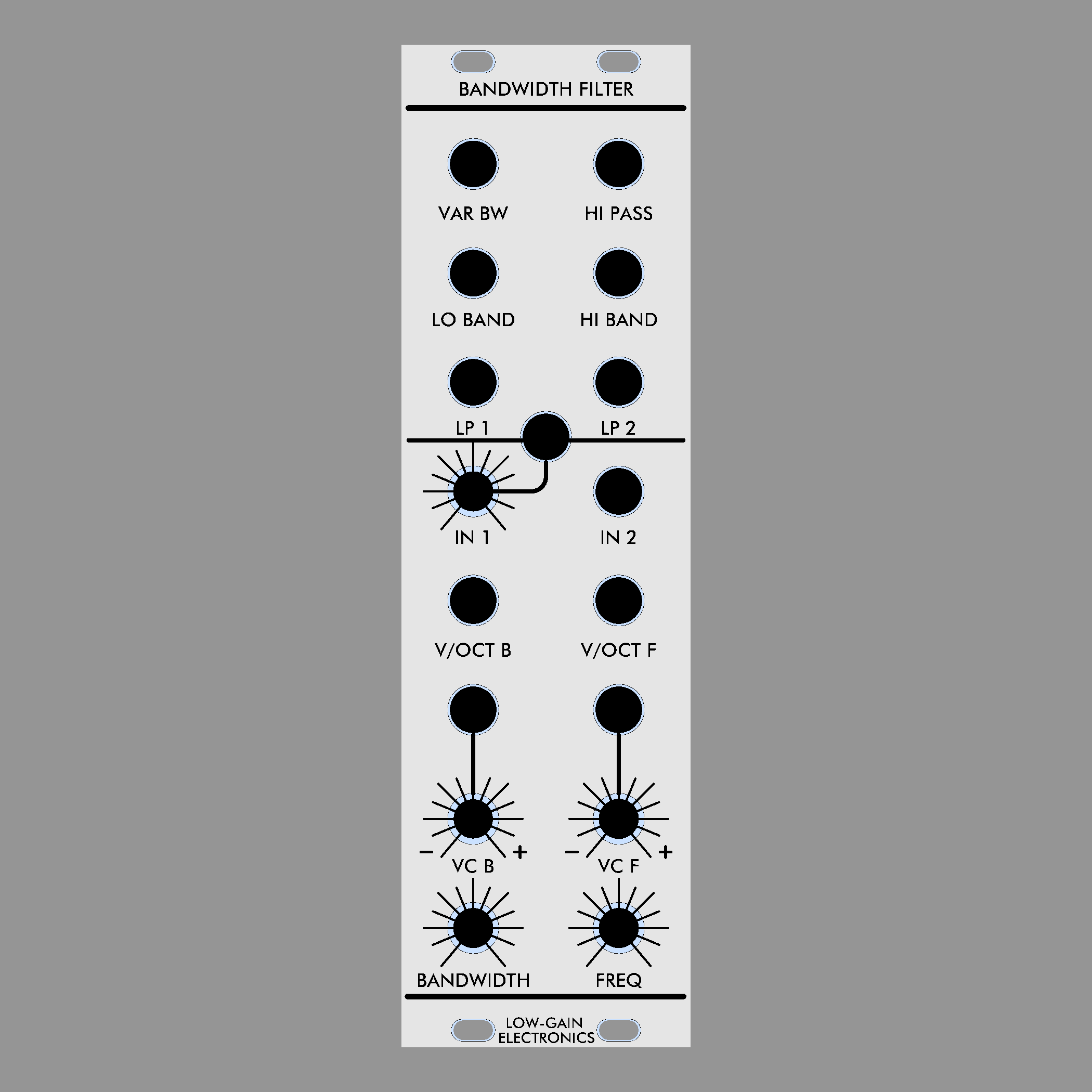
In the Bandwidth Filter, two state-variable VCF's are connected in series to produce a total of six outputs. High pass, low pass 1, low pass 2, two fixed bandwidth outputs . and one variable bandwidth output are available. With an addition input with attenuator you can patch any of the 6 outputs back into the filter to provide resonance (Hi Band output is our favorite for this).
In the Bandwidth Filter, two state-variable VCF's are connected in series to produce a total of six outputs. High pass, low pass 1, low pass 2, two fixed bandwidth outputs . and one variable bandwidth output are available. With an addition input with attenuator you can patch any of the 6 outputs back into the filter to provide resonance (Hi Band output is our favorite for this).
In the Bandwidth Filter, two state-variable VCF's are connected in series to produce a total of six outputs. High pass, low pass 1, low pass 2, two fixed bandwidth outputs . and one variable bandwidth output are available. With an addition input with attenuator you can patch any of the 6 outputs back into the filter to provide resonance (Hi Band output is our favorite for this).
From the original Catalog
“The VARIABLE BANDWIDTH FILTER (VCF2) has a band-pass output which can be varied manually or with voltage control . This is a standard response synthesizer VCF, typical to filters used in many studio systems . In the VCF2, two state-variable VCF's are connected in series to produce a total of five outputs. High pass, low pass, two fixed bandwidth outputs . and one variable bandwidth output are available. The outputs are all flat-response (no resonance) so the VCF2 is suitable for processing concrete sounds without introducing resonant coloration to the timbres . Under voltage or manual control, cut-off frequency of the high and low-pass outputs are affected, as well as the center frequency of the two band-pass outputs. Both center frequency and bandwidth are independently controllable on the variable bandwidth output. ”
In our version, there are 6 outputs (added 2nd LP output) and an addition input with attenuator which will allow feedback (resonance) patches to be made with any of the 6 outputs (hi-band being our favorite to use).
LGE108 have all the SMD parts pre-assembled. You will still need to install 100K trim pot, and headers (and calibrate).
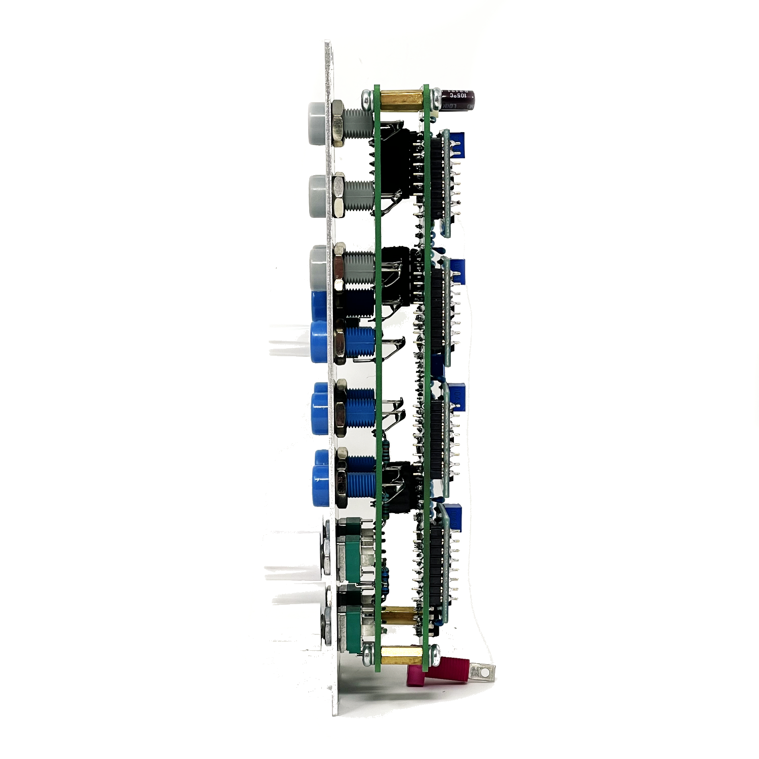
LGE108 Gain cells are sold separately. The Bandwidth Filter requires 4 LGE108 Gain Cells.
Build Info:
LGE110 Main PCB Bill of Materials
LGE110 Main PCB Schematic
LGE110 Main PCB Designators
LGE110C I/O PCB Bill of Materials
LGE110C I/O PCB Schematic (wiring diagram)
LGE110C I/O PCB Designators
LGE108 Gain Cell Schematic
LGE108 Gain Cell PCB Designators
LGE108 Gain Cell Testing/Calibration circuit
LGE108 Gain Cell Requires 100K Trim Pot to be installed prior to installing onto pcb.
Mechanical Parts BOM generally required for building Low-Gain Electronics Modules
** 4U Modular is a term used for the format most commonly known as “Serge Format” or “Loudest Warning Format”. Out of respect for the ever growing format, 4U Modular is the easiest way to refer to it. More Specifically it refers to the panel height and mounting hole style. 4U Modular will patch up just fine with other 4U "Serge" formats such as "Random Source", but it will not mount in RS boats or Buchla Boats (or power off Buchla power for that matter). An info page about this will be added to the website soon to make this a lot more easy to understand.
Assembled Modules are built to order, please be patient when ordering. Use the contact page if you have any questions or requirements!


