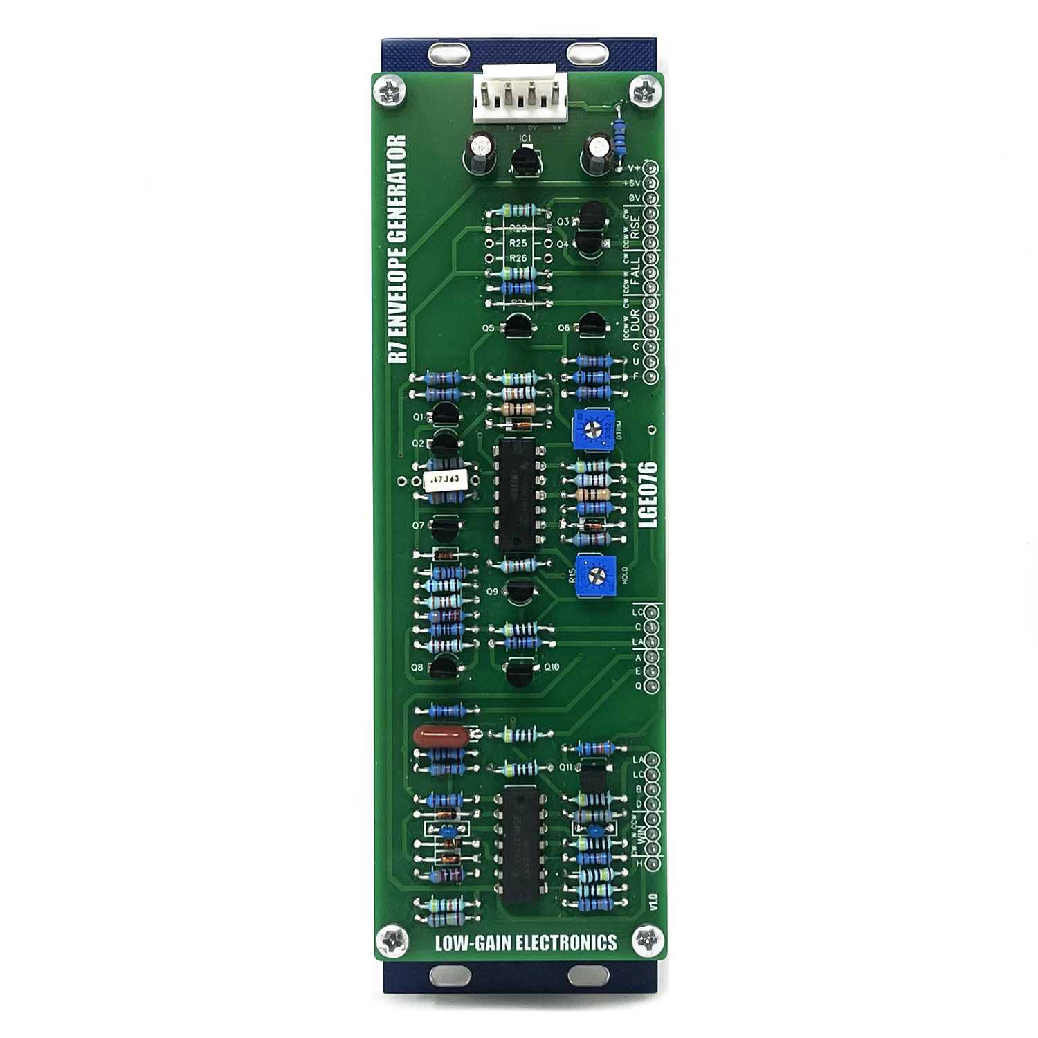
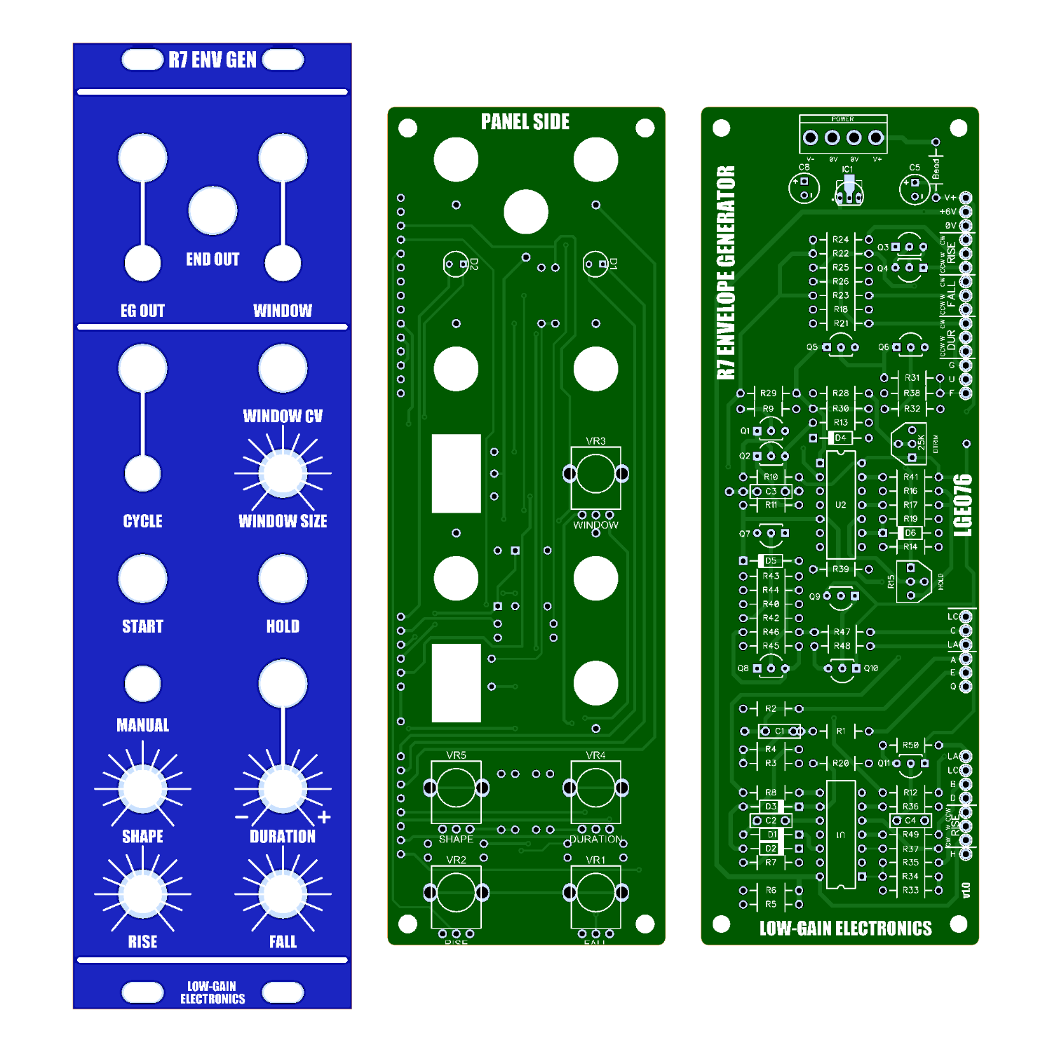
R7 '73 Envelope Generator
The R7 Envelope Generator is a classic function generator circuit from the 73-75 era paperface modular system.
The R7 Envelope Generator is a classic function generator circuit from the 73-75 era paperface modular system.
The R7 Envelope Generator is a classic function generator circuit from the 73-75 era paperface modular system.
The R7 Envelope Generator is a classic function generator circuit from the 73-75 era paperface modular system. With added modifications such as cycle switch, manual start push button and variable shape control (Lin/Expo/Log) of the envelope shape.
Features:
Rise / Fall Controls
Voltage Control over Duration (effects both Rise and Fall rates)
Shape Control (Exponential, Linear and Logarithmic responses)
Start Input (Think of this as your “trigger input”, it starts the EG)
Hold Input (This holds the envelope in it’s cycle when the input goes high/5V at the input)
Cycle Switch (Same as patching End out to Cycle Input, When cycling, the cycle input is not active)
Cycle Input (cycles envelope for as long as the Cycle input is held hi)
Window Size Control (Window comparator for providing a Gate output of specified width of the Envelope Cycle)
Voltage Control over Window Size
Window Output (5V Gate based on the window size)
End Output (outputs a pulse at the end of the Envelopes fall stage)
Envelope Output (0-5V)
Setup (Original CGS Directions)
DTRIM is used to set the initial cycle speed. Turn RISE and FALL to the fasted positions. Adjust DTRIM until you get 4.00 volts on pin 4 of the LM3900 (U2) (NOT the one marked MC3401 on the PCB). I did this with END patched to CYCLE.
The second trim pot is to stabilize the HOLD function. Too high, the signal drifts, too low and the signal "pulses". To adjust this, plug the ENV out into a VCO, then trigger hold during an envelope. Adjust the trimpot using the VCO tone as a guide.
Comments on usage (Original CGS notes)
The HOLD function only works when the Window Pulse Output LED is lit.
The rise and fall pots are wired to control rate, not length. As such they seem backwards for envelope generator functions, but correct for LFO functions.
To use it as a VCLFO, patch end to cycle, and feed a CV into duration.
DIY Build Info:
LGE076 Main PCB Bill of Materials
LGE076 Main PCB Schematic
LGE076 Main PCB Layout w/ Designators
LGE076C I/O Board Bill of Materials (BOM)
LGE076C I/O Board Schematic (Wiring Diagram)
LGE076C I/O Board Layout w/ Designators
Make sure your Cycle Switch is wired CORRECTLY.
Mechanical Parts BOM generally required for building Low-Gain Electronics Modules
** 4U Modular is a term used for the format most commonly known as “Serge Format” or “Loudest Warning Format”. Out of respect for the ever growing format, 4U Modular is the easiest way to refer to it. More Specifically it refers to the panel height and mounting hole style. 4U Modular will patch up just fine with other 4U "Serge" formats such as "Random Source", but it will not mount in RS boats or Buchla Boats (or power off Buchla power for that matter). An info page about this will be added to the website soon to make this a lot more easy to understand.
Assembled Modules are built to order, please be patient when ordering. Use the contact page if you have any questions or requirements!


