


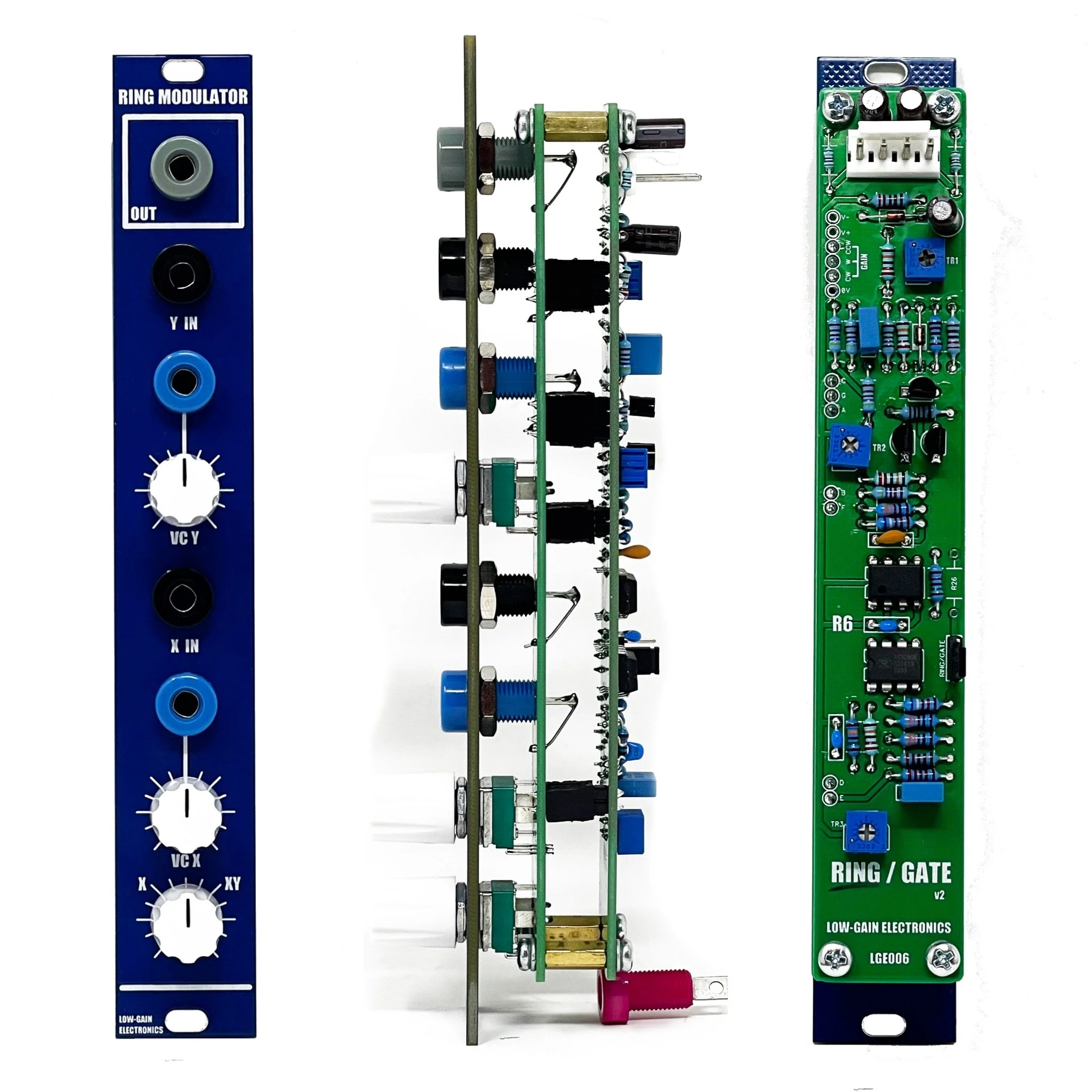


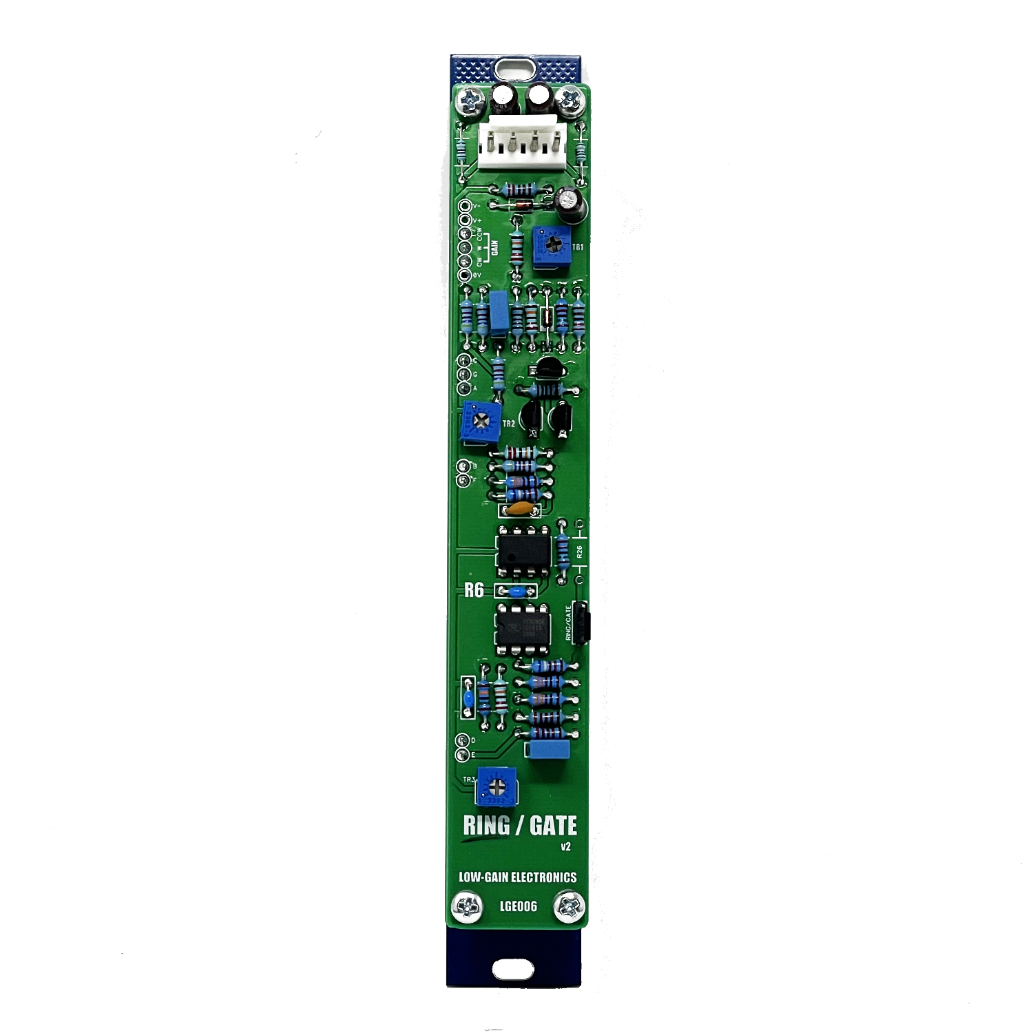


R6 Ring / Gate (Ring Modulator / VCA)
DESCRIPTIONThe classic 2 for 1 VCA/Ring Mod pcb in the 4U Modular DIY format! The LGE006 is two modules in one pcb, it can be built as either a Ring modulator OR a Gate (VCA).
DETAILSDIY PCB
Can be built as either a VCA or a Ring Modulator
Current: TBD
PCB Size: 6” x 1”
DESCRIPTIONThe classic 2 for 1 VCA/Ring Mod pcb in the 4U Modular DIY format! The LGE006 is two modules in one pcb, it can be built as either a Ring modulator OR a Gate (VCA).
DETAILSDIY PCB
Can be built as either a VCA or a Ring Modulator
Current: TBD
PCB Size: 6” x 1”
DESCRIPTIONThe classic 2 for 1 VCA/Ring Mod pcb in the 4U Modular DIY format! The LGE006 is two modules in one pcb, it can be built as either a Ring modulator OR a Gate (VCA).
DETAILSDIY PCB
Can be built as either a VCA or a Ring Modulator
Current: TBD
PCB Size: 6” x 1”
The LGE006 is two modules in one pcb, it can be built as either a Ring Modulator or a Gate (VCA). This classic paperface era module was typically found built side by side with both Ring and Gate features.
From the Catalog:
“The RING MODULATOR/GATE (MOD) is an AC or DC coupled Ring Modulator and VCA featuring
superior audio processing capabilities. The Ring Modulator offers two VC inputs in addition to the two signal inputs
which may be used to perform voltage controlled transitions between full ring modulation and amplitude modulation.
The VCA can be used as a standard voltage controlled amplifier with either log or linear control voltage characteristics.
The DC coupled input is useful for using the VCA as a DC multiplier or gate. ”
A unique feature of this VCA is the Linear CV Input is actually inverted. This will allow you to do some fun tricks when using both CV Inputs. Just be very careful, if your Linear CV signals go negative they have the ability to amplify the signal
to the full rails of power supply making for a VERY loud output! Ear/Speaker damage levels. The added CV Input attenuators will help keep this under control. You have been warned! :)
A bit of history about the original “R6” naming of the PCB…
”R6 - The R stands for Randy Cohen who designed the module’s PCB in 1972, and the 6 designates the Ring Modulator/VCA as being the 6th module in the series of 16 modules which formed the early “People’s Synth” AKA Serge-O-Vox.” - Arpad Benares (3/28/2025)
Read about Randy Cohen here!
For more information on the circuit, Ken Stone provided a great little write up about it here.
Using Ken Stones CGS79 PCB as an example for wiring the panel for the Ring option can be seen here. The Gate
Gate/VCA Trim Instructions:
Input an audio source into the AC-Input.
Set TR3 (R12 on schematic) to center and adjust TR2 (R9 on schematic) for same output amplitude as
Input (unity)
Input DC Source into the DC Input. Adjust TR-1(R5 on schematic) for Minimum output offset
Ring Trim Instructions:
Adjust the panel potentiometer all the way to ground (CW).
Adjust TR3 (R12 on schematic) to center position
Adjust TR2 (R9 on schematic) fully to +V position
Input 500 Hz 0/5V sawtooth into Input X AND pad A (no panel connection)
While looking at the output, adjust TR1 (R5 on schematic) until the output waveform is perfectly symmetrical (and rectified), as
below.
Note that the rectified sawtooth wave has a distinctly rounded bottom.
Now disconnect the sawtooth from Input X (keeping it connected to pad A).
Turn the scope sensitivity up. Adjust TR3 until the least feed through of the sawtooth is seen (or heard).
It would be good to repeat the initial adjustment of TR1 as above, mow that TR3 has been set.
Finally, with the sawtooth still connected to Input X, connect it to Input Y.
Now adjust TR2 to achieve as symmetrical an output at 1000 Hz as possible. Note that the waveform will be
somewhat different to the previous one, due to the non linear characteristic of the transistor pair.
Alternative method:
Set X-XY pot to X (CW).
Connect an audio frequency triangle wave to X input.
Adjust trimmers TR2 (R9 on schematic) and TR3 (R12 on schematic) for minimum breakthrough (Bleed) . This will require alternately adjusting the two trimmers
until you get the desired result.
Move the audio frequency triangle wave to the Y input.
Connect a second triangle wave, this time at around 1Hz, to the X input.
Adjust TR1 (R5 on schematic) for a balanced "throb" .
Quick & Easy calibration for the R6 Ring shown in this video:
DIY Information: (Some older documentation on the original R6)
V2: (clean build, no cuts/mods required)
LGE006 Main Board Bill of Materials V2
LGE006 Main Board Schematic V2
LGE006 Main Board PCB w/ Designators V2
LGE006G Printable Panel Art
LGE006GC I/O Board Schematic / Wiring Diagram
LGE006GC I/O Board PCB w/ Designators
LGE006GC I/O Board PCB Bill of Materials (Coming Soon)
LGE006R Printable Panel Art
LGE006RC I/O Board Schematic / Wiring Diagram
LGE006RC I/O Board PCB w/ Designators
LGE006RC I/O Board PCB Bill of Materials (Coming soon)
V1: (trace cutting required)
LGE006 Schematic
LGE006 PCB w/ Designators
LGE006 Bill of Materials
LGE006 PCB Mod Required for Gate/VCA function
LGE006C Panel Wiring Diagram / Schematic (Ring / Gate)
Mechanical Parts BOM generally required for building Low-Gain Electronics Modules
** 4U Modular is a term used for the format most commonly known as “Serge Format” or “Loudest Warning Format”. Out of respect for the ever growing format, 4U Modular is the easiest way to refer to it. More Specifically it refers to the panel height and mounting hole style. 4U Modular will patch up just fine with other 4U "Serge" formats such as "Random Source", but it will not mount in RS boats or Buchla Boats (or power off Buchla power for that matter). An info page about this will be added to the website soon to make this a lot more easy to understand.
Details:
PCB Size: 6” x 1”
Current Draw: TBD
TR1 = Y “GAIN”/”SYMMETRY” TRIM
TR2 = Y OFFSET TRIM
TR3 = X OFFSET TRIM (OUTPUT OFFSET)