
 Image 1 of 3

Pan/Fade – Voltage-Controlled Panning & Crossfading Module
Pan/Fade is a versatile reinterpretation of the original Active Processor circuit, designed to offer two powerful functions in one compact module: linear voltage-controlled panning and VC crossfading. Built on the same flexible foundation as the original Active Processor circuit, this module unlocks new patching possibilities for both audio and CV routing.
🌀 Dual Modes of Operation
Pan Mode:
Route a single input to either of two outputs under voltage control.Input 1 is active (Input 2 is ignored)
The VC Pan input directs the signal to Output 1, Output 2, or any blend in between
Perfect for stereo spatialization or automated routing
Fade Mode:
Crossfade smoothly between two input signals using a CV or manual control.Both Input 1 and Input 2 are active
Only Output 1 is used
Ideal for morphing between CV sources, waveforms, or audio tracks
Mode switching is handled via a front-panel toggle, making it easy to shift functions on the fly during a patching session.
📜 Inspired by the Original Serge Design
From the original SMMS catalog:
“The ACTIVE PROCESSOR (ACPR) is an accurate, linear cross-fader for either control voltages or audio signals. This module provides an important link in complex patches, allowing the user to smoothly change from one control voltage to another...”
In the spirit of the original, the Pan/Fade remains true to its purpose as a clean, accurate processor for both audio and CV, while expanding its functionality with a user-selectable mode switch. Whether you're sculpting sound or shaping modulation, Pan/Fade offers precise control and elegant utility in a single module.
** 4U Modular is a term used for the format most commonly known as “Serge Format” or “Loudest Warning Format”. Out of respect for the ever growing format, 4U Modular is the easiest way to refer to it. More Specifically it refers to the panel height and mounting hole style. 4U Modular will patch up just fine with other 4U "Serge" formats such as "Random Source", but it will not mount in RS boats or Buchla Boats (or power off Buchla power for that matter). An info page about this will be added to the website soon to make this a lot more easy to understand.
DIY Information:
LGE201P Main PCB Bill of Materials
LGE201P Main PCB Schematic
LGE201P Main PCB Designators
LGE201PC I/O PCB Bill of Materials
LGE201PC I/O PCB Schematic
LGE201PC I/O PCB Designators
Calibration: Read Me
Mechanical Parts BOM generally required for building Low-Gain Electronics Modules
One thing to understand about this type of circuit… like the Universal Audio processor, ACP or other similar circuits: If your Pan/Fade Bias control is in the full clockwise position, and you are
feeding CV In, you will get more gain from the 2nd VCA than unity because of the nature of summing both the Bias CV as well as the external CV. It’s just the nature of the circuit. If you’re building the module. you could consider
a 5V1 Zener Diode from Pin 6 of U2 to ground. I haven’t tested this, but it may help. It’s how the original circuit works, and I wanted to make sure the users aren’t scratching their head thinking it’s not working correctly. This
is also the same issue on the Stereo Mixer. It has a reputation of having a very hot output.
Details:
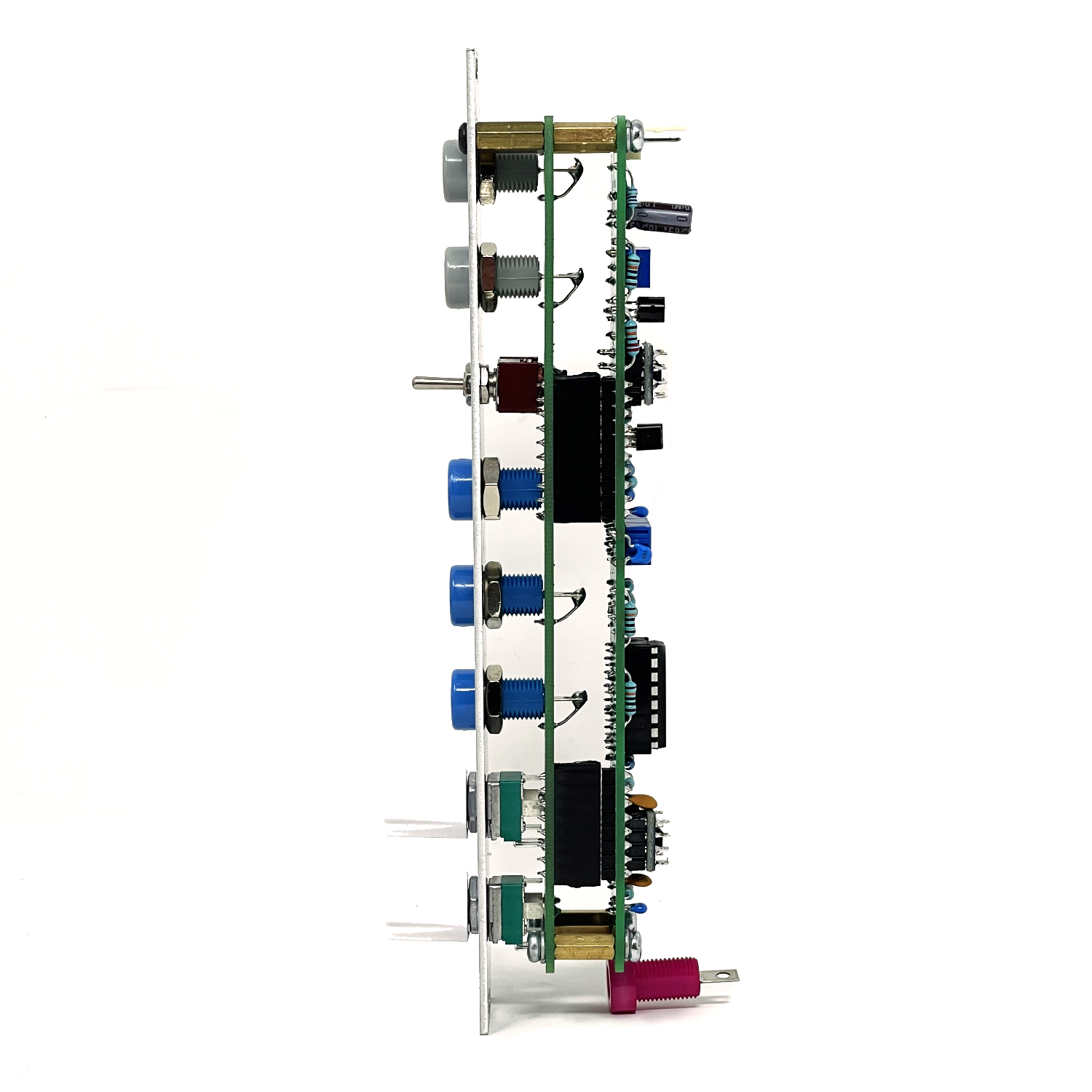
PCB Size: 6” x 1”
Current Draw: TBD