
 Image 1 of 14
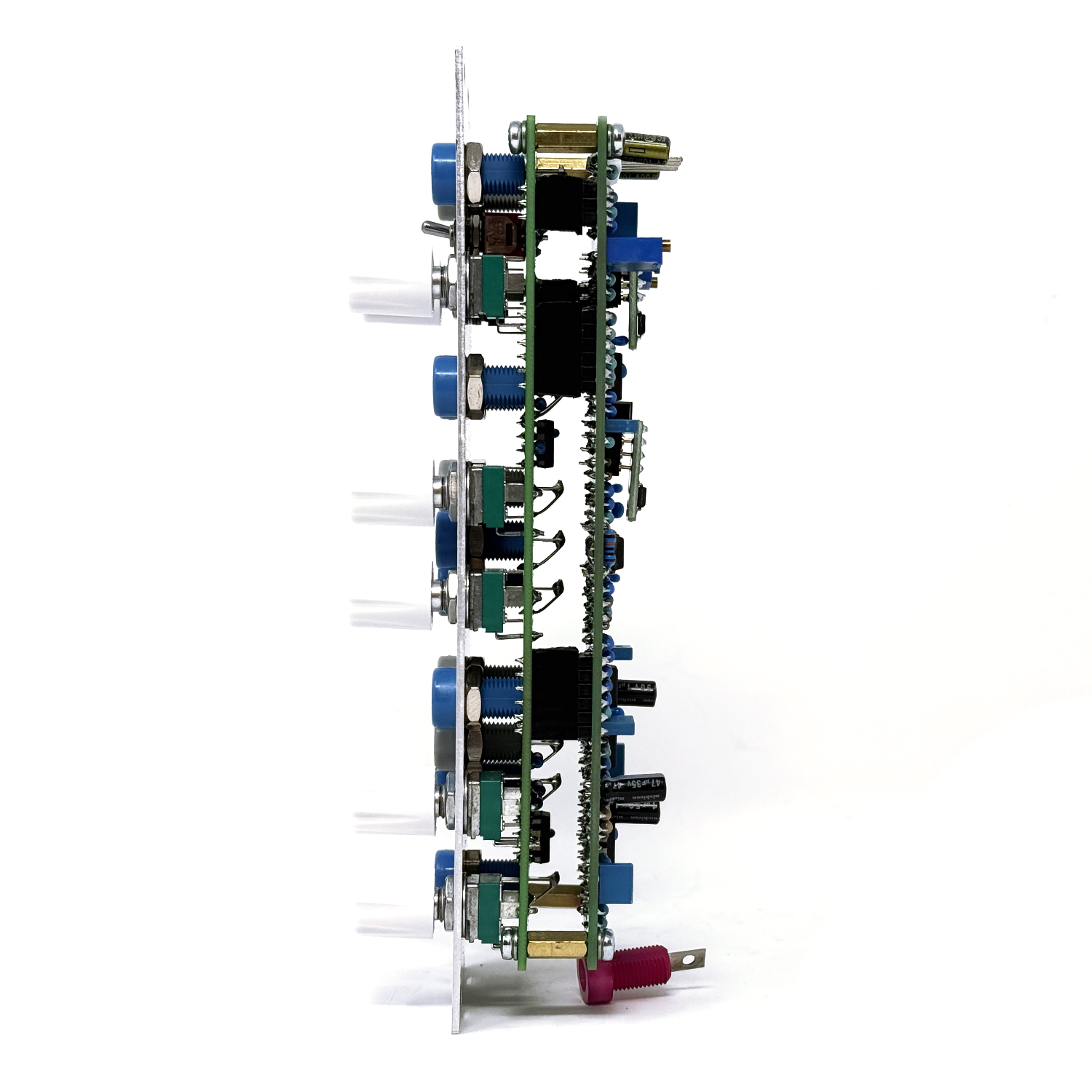 Image 2 of 14
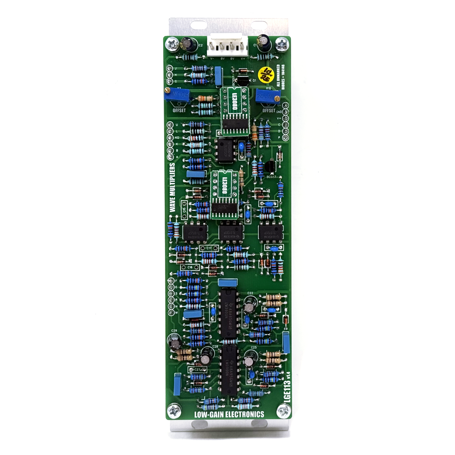 Image 3 of 14
 Image 4 of 14
 Image 5 of 14
 Image 6 of 14
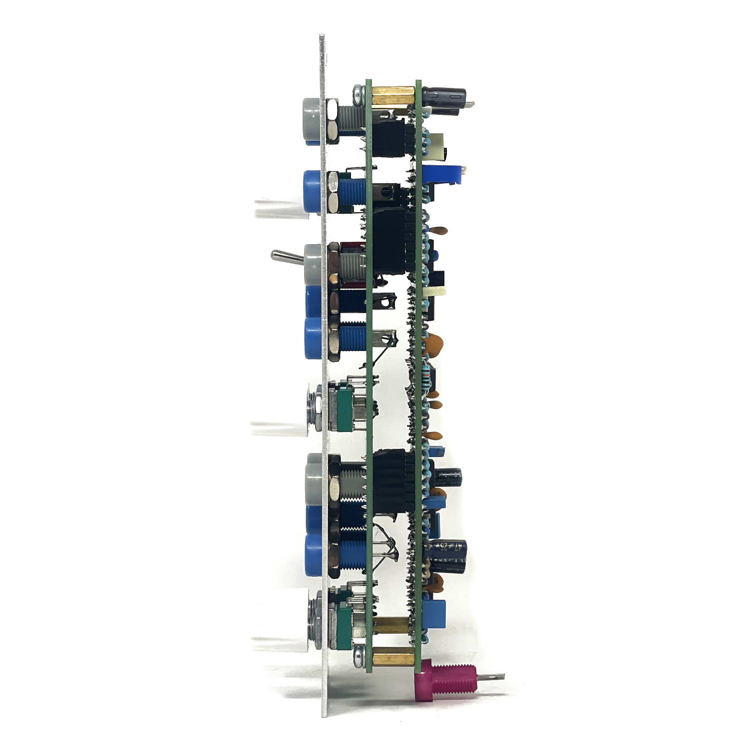 Image 7 of 14
 Image 8 of 14
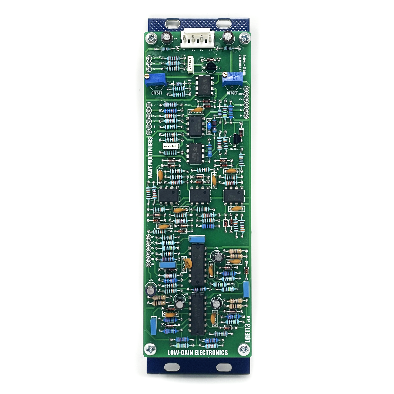 Image 9 of 14
 Image 10 of 14
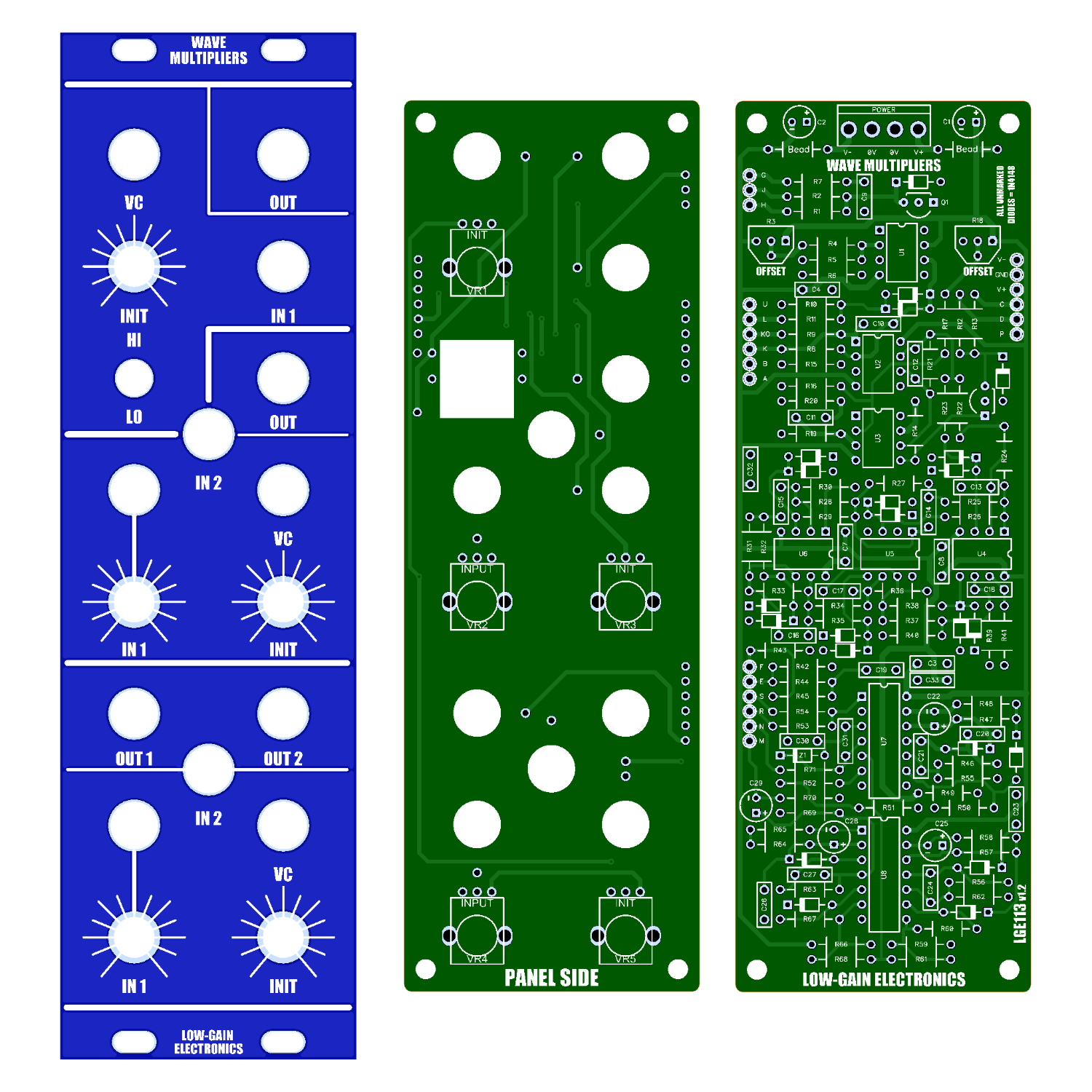 Image 11 of 14
 Image 12 of 14
 Image 13 of 14
 Image 14 of 14
Assembled Modules are built to order, please be patient when ordering. Use the contact page if you have any questions or requirements!
Harmonic Processors (Wave Multipliers) Module – Description & Assembly Guide
This module is based on the classic Serge Wave Multipliers.
Overview
Traditional analog synthesizer patches often follow a linear signal path: VCO → VCF → VCA, with modulation via keyboard, sequencer, or computer. While the VCO generates the sound, the VCF alters timbre through subtractive filtering, and the VCA shapes amplitude and dynamics.
The Harmonic Processors introduce a new element into this chain, offering additive, non-linear wave shaping for richer, harmonically complex timbres. Placed before the VCF, this module doesn't filter out frequencies—it adds harmonics and transforms waveforms in dynamic, controllable ways. Unlike ring modulation, this process works with a single audio input and yields results that are uniquely expressive.
There are three independent wave multiplier circuits in this module, each offering different sonic capabilities. Together, they form a powerful toolset for generating timbres previously limited to acoustic instruments or complex digital processing.
Functionality
Top Section – Dual Mode Distortion / VCA
HI Mode: Applies soft, voltage-controllable waveform clipping, akin to overdriving a tube amp—rounded, saturated distortion rather than hard-edged clipping.
LO Mode: Functions as a linear VCA, ideal for amplitude modulation and gating into other sections of the module.
Middle Section – Odd Harmonic Sweeper
Generates odd harmonics (1st to 13th) by processing an input sine wave.
CV or manual sweep controls harmonic content—comparable to overblowing a wind instrument.
Includes a second input for mixing two signals before processing, yielding complex, evolving textures beyond traditional ring modulation.
Bottom Section – Even Harmonic Wavefolder
Uses three cascaded full-wave rectifiers to shape and double input frequencies.
Adds even harmonics (2nd, 4th, 8th, etc.) while maintaining output amplitude.
Produces smooth timbral transitions and rich sonorities.
Dual inputs and dual outputs, including a squared-up variant similar to advanced PWM.
Sound Design Potential
The Harmonic Processors (Wave Multipliers) enable radical timbral modification that far exceeds conventional analog capabilities. These modules deliver a level of harmonic complexity and expressiveness typically associated with acoustic instruments. Precise control voltage response ensures both creative flexibility and technical reliability, whether you're building chaotic textures or fine-tuned tones.
Power Compatibility
This module operates on either ±12V or ±15V without modification. Note: On ±15V, input sensitivity and output levels increase proportionally.
Assembly Instructions
Pre-Assembly Checklist
Inspect the PCB for etching faults, shorts, or broken traces.
Sand the board edges if necessary to remove roughness.
Assembly Order
Start with resistors.
Proceed to IC sockets (if used).
Finish with taller components (capacitors, transistors, connectors).
Pay close attention to polarized components (electrolytics, diodes, transistors, ICs).
IC Insertion Tips
Ensure the IC notch aligns with the PCB overlay.
Avoid bending pins under the chip during insertion.
Component Notes
Although the PCB specifies 4558 dual op-amps, TL072 is recommended for stability.
When using alternate op-amps, verify they don’t self-oscillate. In some builds, 47pF capacitors across specific op-amp pins (e.g., pins 6–7 of the top 4558) were needed for stability.
Building Notes
After assembly, ensure the PCB is thoroughly cleaned. I recommend using 99% isopropyl alcohol to remove any residual flux, which can sometimes cause unwanted noise or crackling in the audio signal.
In the bottom section, there are three feedback capacitors—C21, C24, and C27—that often introduce more issues than benefits in this circuit.
If Output 1 sounds overly "hum-like", it’s likely due to C27. Removing it usually resolves the issue.
These caps are traditionally used to suppress oscillation, but in this case, I recommend omitting them entirely unless oscillation is actually present.
The Z1 zener diode was originally specified as 4V3 or 4V6, but through testing, I’ve found that a 5V1 or 5V6 zener works better in most builds.
To determine if the *47pF (1) stability capacitors are needed (in the middle section), monitor the output with an oscilloscope:
If you observe oscillation, temporarily install the 47pF caps one at a time from right to left.
After each installation, check the output on the scope.
You’ll typically see the oscillation subside as the necessary caps are added.
Install only as needed—this issue doesn't always occur but can crop up depending on component tolerances.
Conclusion
The Harmonic Processors (Wave Multipliers) represent one of the most versatile and powerful timbral-shaping tools in analog synthesis. With three distinct processing modes and deep voltage control, this module opens up a world of sonic possibilities—ranging from subtly enhanced tones to entirely new acoustic-like textures.
Calibration Procedure
Top Section Trim
Input: 1kHz audio signal into the VC input
Monitor: Output via oscilloscope or by ear
Adjust: R3 trimmer (right side of PCB)
Goal: Minimize CV bleed at the output
Middle Section Trim
Input: 1kHz audio signal into the VC input
Monitor: Output via oscilloscope or by ear
Adjust: R18 trimmer (left side of PCB)
Goal: Minimize CV bleed at the output
Alternative Method:
Leave all inputs unconnected
Monitor output with an oscilloscope
Adjust offset for output as close to 0V as possible
** 4U Modular is a term used for the format most commonly known as “Serge Format” or “Loudest Warning Format”. Out of respect for the ever growing format, 4U Modular is the easiest way to refer to it. More Specifically it refers to the panel height and mounting hole style. 4U Modular will patch up just fine with other 4U "Serge" formats such as "Random Source", but it will not mount in RS boats or Buchla Boats (or power off Buchla power for that matter). An info page about this will be added to the website soon to make this a lot more easy to understand.
DIY Build Info:
MOUSER CART - Does not include headers, stand offs, screws, pots or knobs. Most of these items can be obtained at Tayda Electronics (check Mechanical Parts BOM) (Toggle specified on mouser cart is flat bat and the bushing is just a little too large for the hole, you can drill it out to size or order Tayda part number: A-3188)
LGE113 Main Board Bill of Materials
LGE113 Main Board Schematic
LGE113 Main Board Designator Layout (There is an error on LGE113 v1.2 pcb’s: The 3 Pin header w/ J, H and G are wired incorrectly between LGE113 and LGE113C. They will need to be connect with wires instead of male and female headers. v1.4 is ok w/o any modifications)
LGE113C I/O Board Bill of Materials
LGE113C I/O Board Schematic (Wiring Diagram)
LGE113C V2 I/O Board Correction (Oops) (3 Jacks pinned incorrectly)
LGE113C I/O Board Designator Layout
LGE113 Printable Panel Art
Mechanical Parts BOM generally required for building Low-Gain Electronics Modules

Correct HI / LO switch wiring
Wave Multipliers Panel
Details:
PCB Size: 6” x 2”
Current Draw: TBD