
 Image 1 of 9
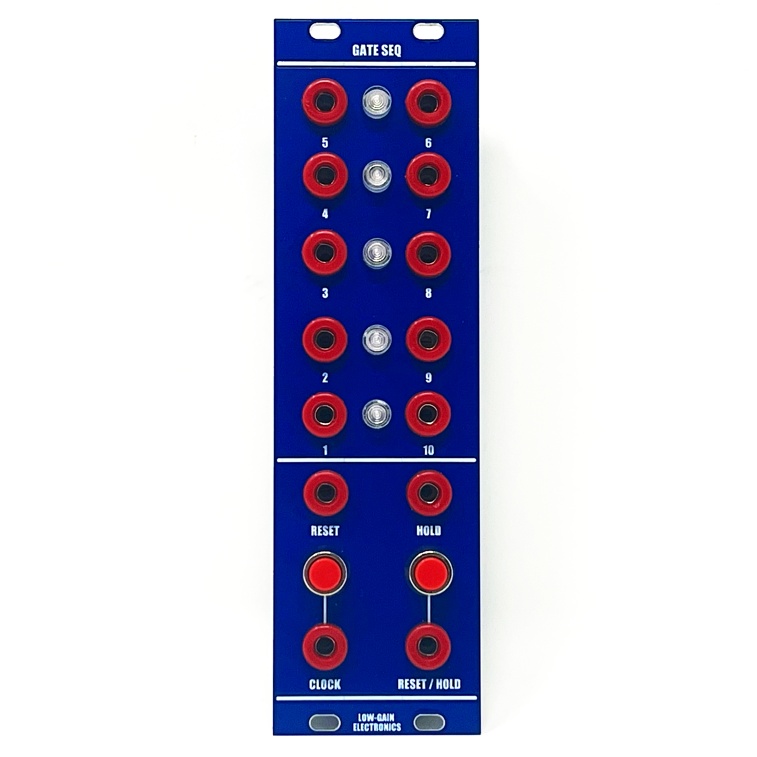


Gate Sequencer – 10-Stage Decade Counter
The Gate Sequencer is a 10-stage sequential gate module with individually stackable gate outputs per stage. Each rising edge at the Clock input advances the counter by one stage. When stage 10 is reached, the next clock pulse resets the sequence to stage 1.
Flexible sequence lengths can be achieved using the Reset or RST/HLD inputs. The Reset input immediately resets the counter to stage 1 upon receiving any gate or trigger. The RST/HLD input behaves like a gate: when held high, it locks the sequencer at stage 1 until the input goes low, at which point counting resumes with the next clock pulse.
A separate Hold input freezes the sequence at the current stage, regardless of its position, and resumes counting once the input returns low. Manual pushbuttons for both Clock Advance and RST/HLD are provided for hands-on control.
Each stage output is a steady 5V gate (not a trigger) that remains high while its corresponding stage is active. Outputs are stackable and behave like an OR logic bus, making it easy to build complex gate patterns, trigger other sequencers, or generate CVs by routing stage outputs through a matrix mixer or voltage processor.
Dual-color LEDs indicate the current stage: one color for stages 1–5 and another for stages 6–10, providing clear visual feedback.
Extended Description
The Gate Sequencer offers a straightforward yet powerful way to create rhythmic gate patterns, clock divisions, and control signals for modular systems. Because each stage output provides a full 5V gate signal, it interfaces cleanly with logic processors, switch modules, and clocked CV sources. By stacking outputs with patch cables, users can build composite rhythms and temporal events, turning the sequencer into a flexible timing brain.
10 stages with individual gate outputs
Manual Clock and RST/HLD pushbuttons for real-time interaction
Reset input (trigger or gate) resets to stage 1 instantly
RST/HLD input (gate) holds the sequencer at stage 1 while high
Hold input (gate) freezes the current stage until released
Stackable outputs for OR logic pattern building
Dual-color LED indicators show sequence position at a glance
Whether used for complex gate sequencing, synchronized modulation, or CV step creation via gate-to-voltage conversion, the Gate Sequencer is a valuable utility in any timing-centric patch.
Need a quick Toggle/FlipFlop? Patch Stage 3 output to Reset input, use the Clock input as your control input, Stages 1 and 2 become your Q and Q Not outputs! Instant Sub-Octave divider!
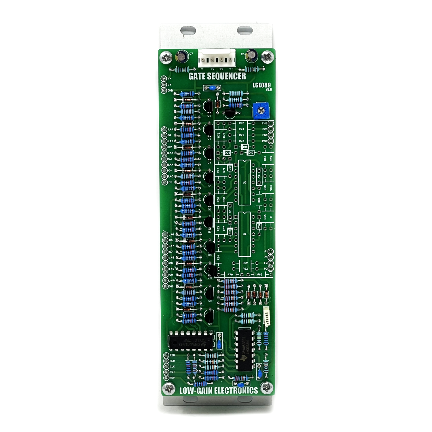
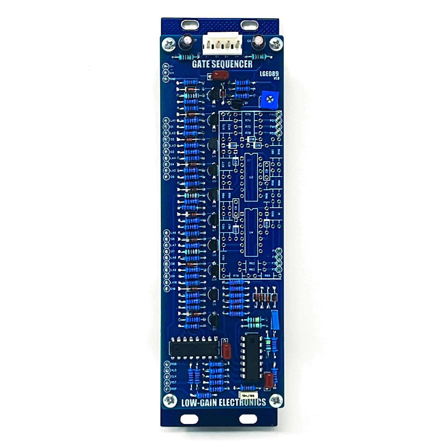
DIY Build Documentation:
Main PCB Bill of Materials (LGE089)
Main PCB Schematic (LGE089)
Main PCB Layout w/ Designators (LGE089)
LGE089C V1 I/O Board:
Gate Sequencer I/O PCB Bill of Materieals (LGE089C) (Tayda: A-806 MTA100 for V1.3 Green PCB)
Gate Sequencer I/O PCB Schematic (LGE089C)
Manual Advance Modification Image
Gate Sequencer I/O PCB Schematic (LGE089C) w/ Modification
LGE089C V2.1 (White Panel Pushbutton on Bottom row configuration):
LGE089C V2.1 I/O Board Bill of Materials
LGE089C v2.1 I/O Board Schematic
LGE089C v2.1 I/O Board Layout w/ Designators
Mechanical Parts BOM generally required for building Low-Gain Electronics Modules
**The parts located within the white outlined box on the PCB are used for the Gate Sequencer XL. They do not need to be installed for use w/ this version of the module.
** 4U Modular is a term used for the format most commonly known as “Serge Format” or “Loudest Warning Format”. Out of respect for the ever growing format, 4U Modular is the easiest way to refer to it. More Specifically it refers to the panel height and mounting hole style. 4U Modular will patch up just fine with other 4U "Serge" formats such as "Random Source", but it will not mount in RS boats or Buchla Boats (or power off Buchla power for that matter). An info page about this will be added to the website soon to make this a lot more easy to understand.
Details:
PCB Size: 6” x 2”
Current Draw: TBD